Wanhao Duplicator i3 with BLTouch Bed Leveling
Automatic bed leveling on the Wanhao Duplicator i3 with the BLTouch bed leveling sensor
TL;DR - Add BLTouch automatic bed leveling to the Maker Select v2.1 using the stock mainboard and LCD and keeping SD card support.
The MonoPrice Maker Select v2.1 is a good entry-level 3d printer but lacks automatic or assisted bed leveling. Given its 4-point bed leveling, it can be a challenge to level. This tutorial will explain how you can improve your bed leveling experience with either assisted bed leveling or fully automatic bed leveling with the addition of a BLTouch sensor.
Which Printer Are We Talking About
The Maker Select v2.1 is a different printer than the MonoPrice Maker Select Plus or Mini and should not be confused with them. The Maker Select v2.1 is a rebranded version of the Wanhao Duplicator i3 and any parts or tutorials should be interchangeable between those two printer. In Australia the printer is sold as a Cocoon Create. For the rest of this tutorial I'll refer to the printer as an i3.
Types of Bed Leveling
The i3 has 4 thumbscrews that you must turn to raise or lower the bed while also moving the nozzle. Typically your goal is to get a piece of paper to barely fit between the nozzle and the bed at each corner of the bed. Making the process more difficult, you have to manually move the nozzle to each corner of the bed by adjusting the X and Y position and you often have to do it multiple times.
Corner Leveling
Some 3D printer have a software feature that is sometimes called leveling assist. Leveling assist is an interactive menu that will automatically move the nozzle from one bed corner to the next at the push of a button. You still have to raise and lower the bed manually but the process is a lot less difficult.
Automatic Bed Leveling
An even better type of leveling is automatic bed leveling. With this form of leveling the bed does not have to be level. Instead a probe is used to obtain the bed height at a sampling of points. Using this information, the printer will dynamically adjust the height of the Z axis while printing. This means you can get great first layer prints without a perfectly level bed.
Manual Probing
You can use the paper test to gauge the height of multiple points on the bed to perform automatic bed leveling. It is not as good as having a sensor because it is time consuming. You won't want to automatically level the bed with manual probing before each print but manual probing can still be beneficial. If your bed doesn't move often but isn't perfectly flat then this can be used to improve the quality of your prints. For example, many people upgrade the Y carriage plate to a thicker one because plate included in with the printer is known to warp causing the bed to be difficult to level.
Sensor Probing
Sensor probing it what you want if you can afford it. This method uses a sensor to measure the distance between the bed and the nozzle and can optionally be added to the start of every print so that you get a great first layer every time even if your bed shifts. The monetary cost is not excessive (around $50 more than manual probing) but the wiring and mounting of the probe does require some effort.
Hardware
Before getting to far into this tutorial it should be mentioned that in addition to the i3 printer you'll also need additional hardware.
Hardware Needed
Adding any of the bed leveling methods to the i3 will require you to replace the firmware on your printer. To do this you will need an Arduino and some wires. An Arduino Uno works well for this purpose and many people already have one. If you don't have one you can either buy one for around $20 or borrow one from a friend. After an initial procedure you won't need the Arduino any more.
To use sensor based leveling you'll need a sensor. One of the most popular choices is the BLTouch with 2M extension cable. A 10 pin male cable header will be needed to wire in the sensor to the motherboard. I'd also recommend a new 10 pin cable because I found it using a new 10 pin cable easier than to try to reuse the one already in the system.
UPDATE: I found someone selling pin 27 adapter board for the Duplicator i3 and unlike all the other pin 27 boards that only work for the Creator Ender 3, this one looks like it might be specific to i3. I haven't tried it but its cheap and easier than building your own cable so I'm putting a link here if someone wants to try it - https://www.th3dstudio.com/product/ezout-pin-27-kit-for-wanhao-i3-melzi-board-filament-sensor-or-bl-touch/
You'll need to print out a BLTouch mount from Thingverse and will need some M3 bolts and nuts for the mount you choose. PRINT YOUR MOUNT BEFORE YOU ATTEMPT TO WIRE IN YOUR BLTOUCH. Make sure it fits with your fan configuration. You'll need to adjust the #define X_PROBE_OFFSET_FROM_EXTRUDER and #define Y_PROBE_OFFSET_FROM_EXTRUDER values in the firmware's Configuration.h file to match your mount.
If you'd like keep the wiring organized you will also want to get some small zip ties.
Hardware installation
You must get the BLTouch's 5 wires from the hotend area to the inside of the control box so they can be connected to the mainboard. I spent the time to disconnect the flexible cable housing and run the wires inside of the housing with the other wires. It took about 1.5 hours. You could always zip tie the wires along the outside.
BLTouch Power and Signal Wiring with an A4 Cable
There are 3 BLTouch wires for signal, ground, and 5v positive power that you must connect to the EXT header of the Melzi mainboard. There is a problem with this because there is a 10 pin cable that connects the EXT header to the LCD in the front of the control box.
The pin labeled A4 connects to the speaker on the LCD board, we must disconnect it from the speaker and connect it to the BLTouch signal wire. The remaining 9 pins should stay connected to the LCD but the GND and 5V pins need to also be connected to the BLTouch.
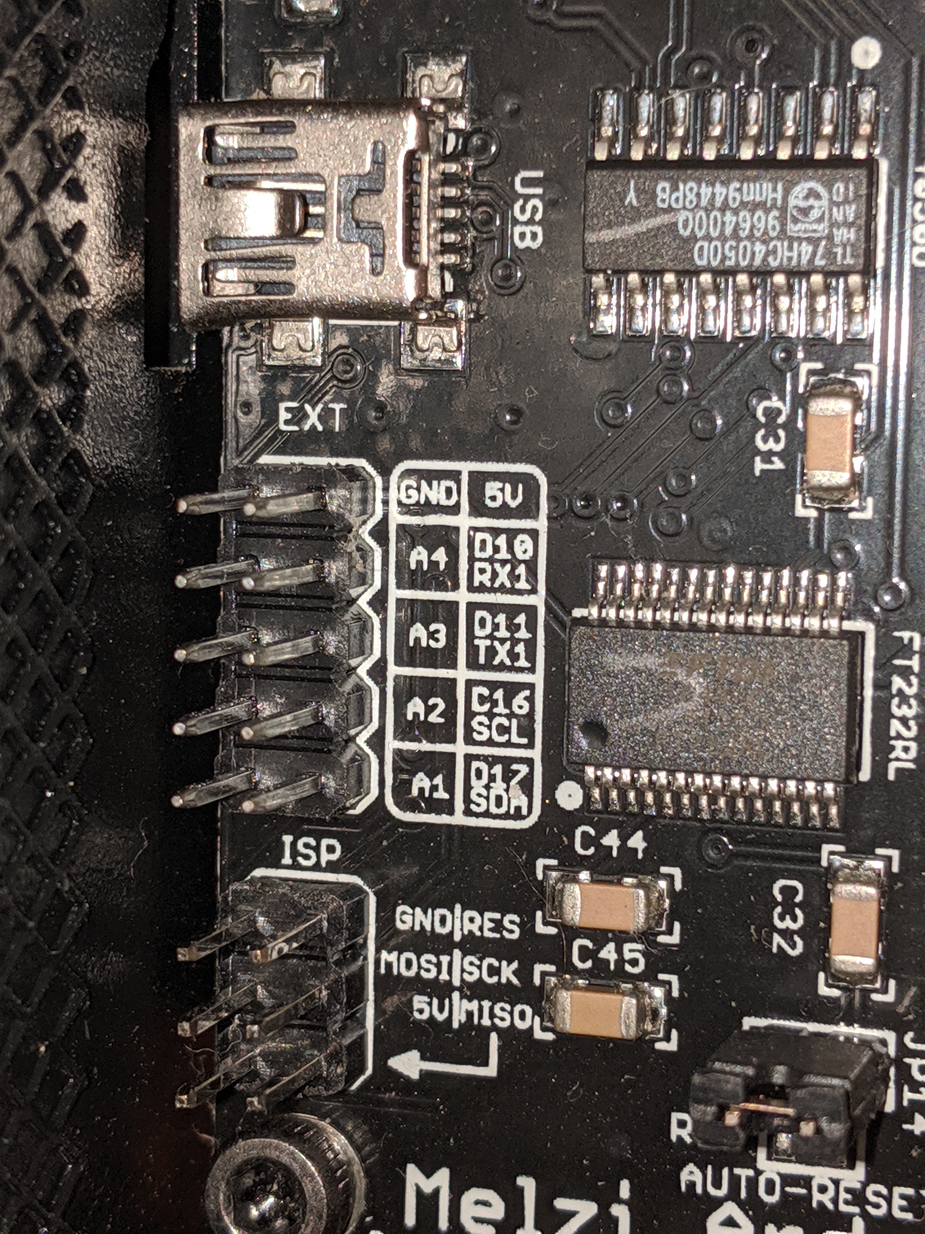
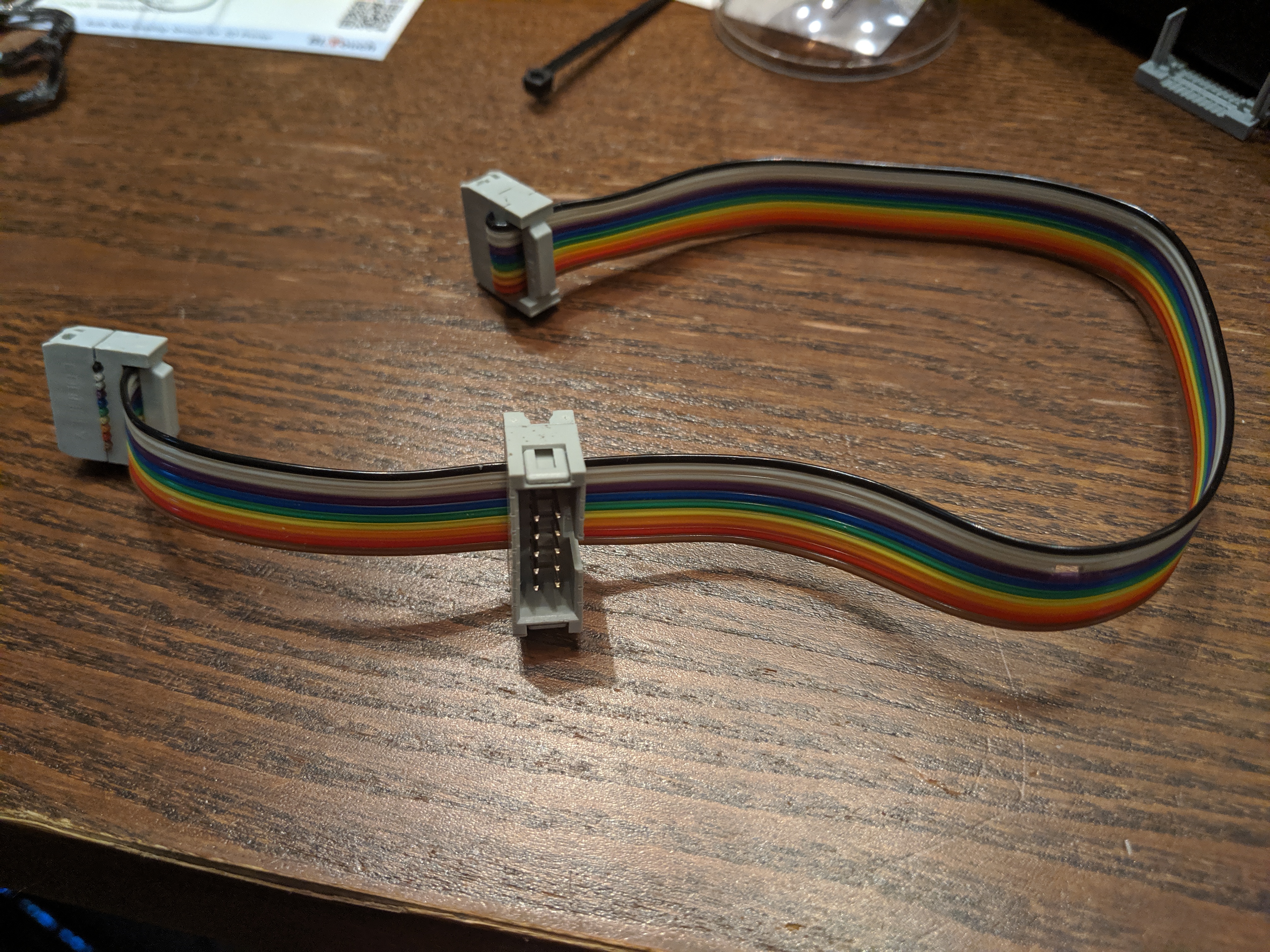
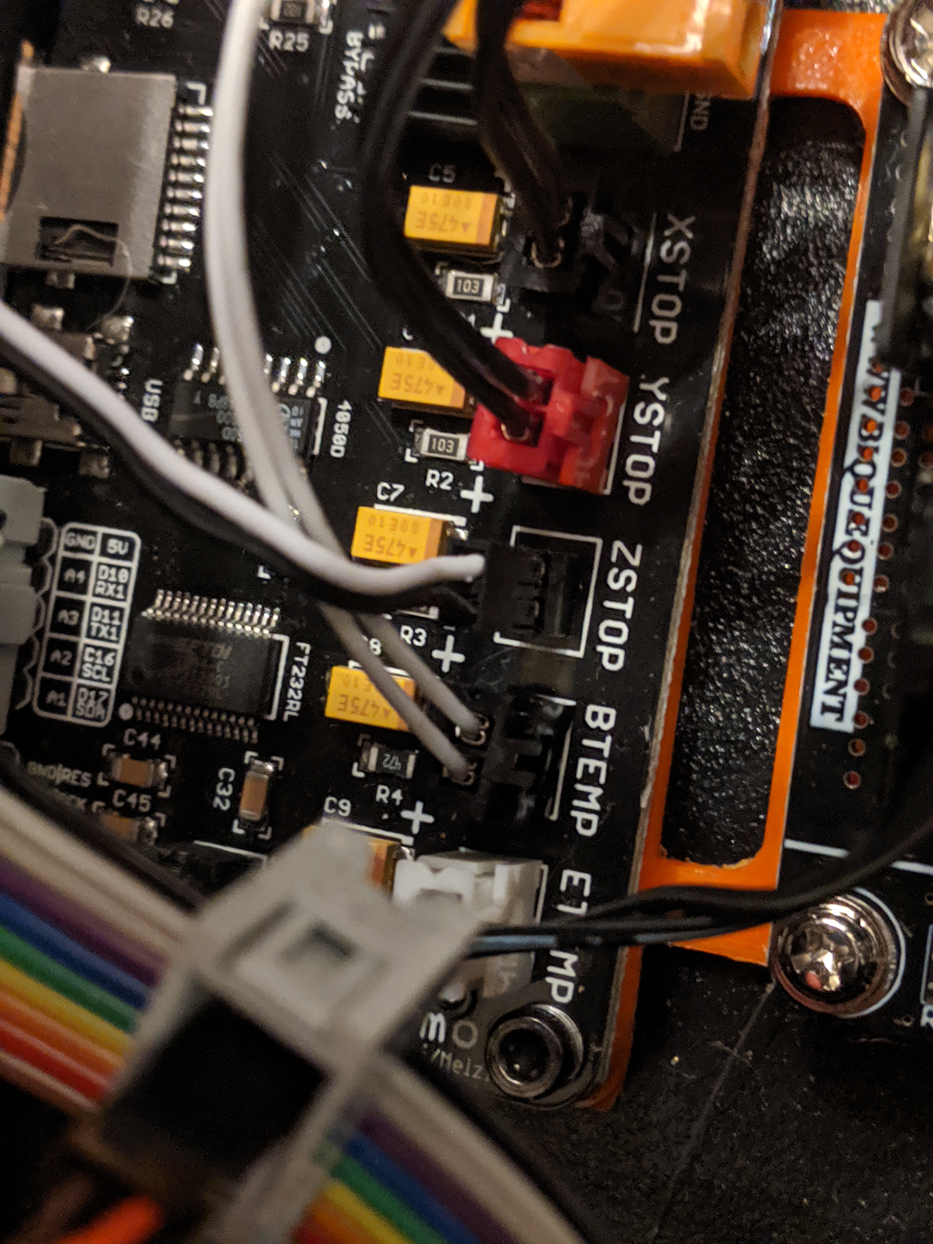
Instead of soldering anything we can build a cable. Add a shrouded 10 male connector to a 10 pin cable with female ends. You can try to use the existing 10 pin cable but I wanted to keep it as-is in case I wanted to go back to stock. You must cut out a portion of the 3rd wire which is the gray wire shown in the picture. The side of the cable with the notch taken out will be connected to the LCD so that the A4 pin is no longer connected to the speaker.
The other female end of the cable connects to the EXT header on the Melzi mainboard. Make sure to connect the cable so that the wire with the notch connects to the A4 pin.
Connect the power and signal BLTouch wires to the male 10 pin header as shown below.
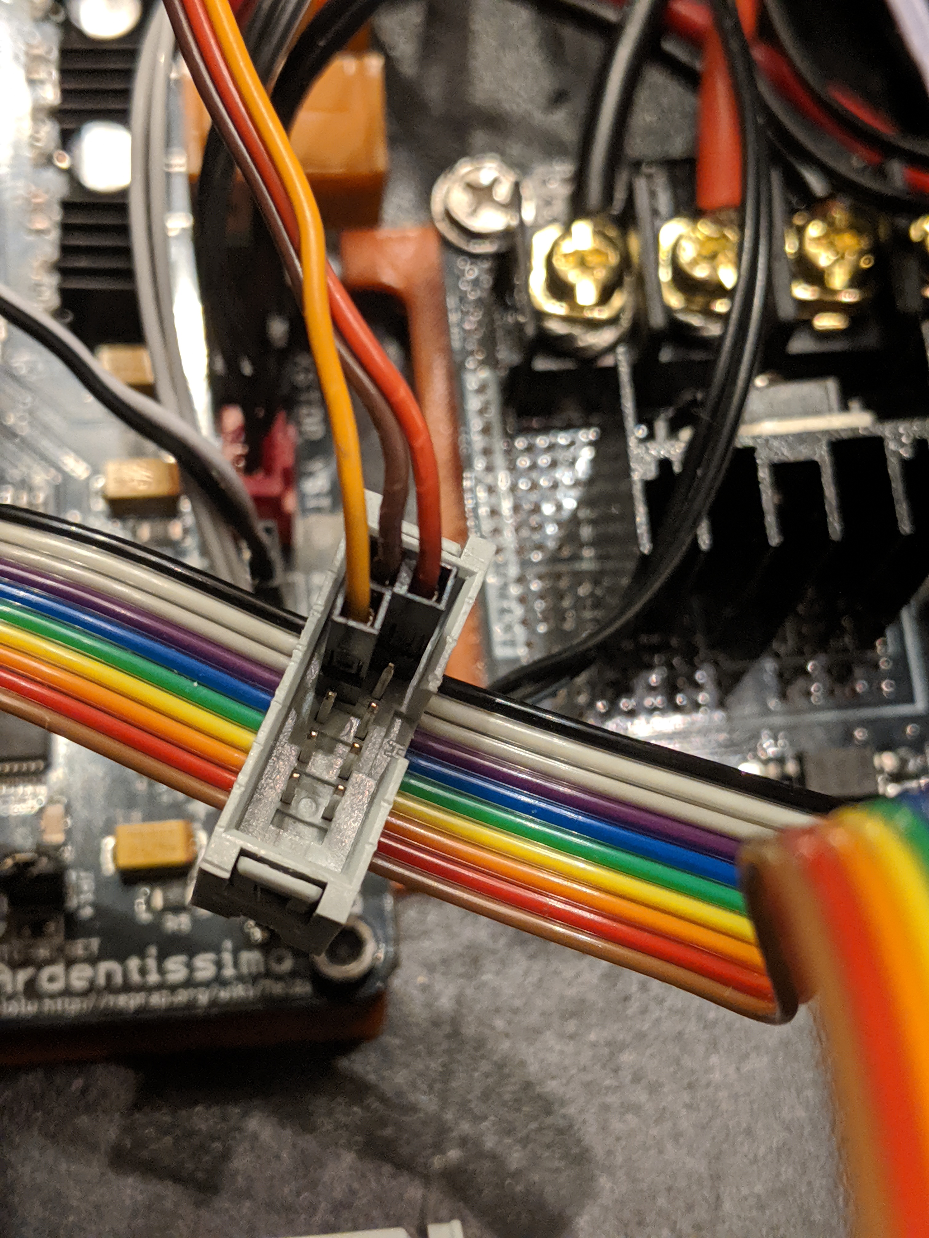
The wiring is also shown in the Melzi & Compatible section of the official BLTouch wiring instructions. The official instructions correctly label the A4 pin but mislabel it D28. For the Melzi board in the i3 the A4 pin is connector 27 instead of 28. This is important for the #define SERVO0_PIN 27 line in the Configuration.h file.
The official instructions say to remove (break off) the C7 capacitor for versions 3+ of the BLTouch. I have NOT done this and so far have had no problems with a v3.0 BLtouch manufactured on April 22 2019.
C7 problems potentially include inaccurate readings or the BLTouch signal not being detected which could result in your nozzle crashing into your bed while homing. When first testing your BLTouch make sure you trigger it by hand well above the bed so you can turn off the power if the printer does not recognize the signal.
Thanks goes to https://3dprinterwiki.info/wiki/wanhao-duplicator-i3/part-specifications/ and https://www.thingiverse.com/groups/i3/forums/general/topic:30927 for providing information about A4 actually being pin 27 on the i3.
BLTouch Z-Stop Wiring
You'll need to disconnect the existing Z-stop switch from the Melzi board and connect it to the BLTouch instead. The old switch will no longer be used.
Because the BLTouch extension cable uses dupont connectors and the mainboard has jst connectors on the later revisions of the i3, I found it easiest to pull off the jst connector which should leave the pins. There might be some hot glue holding the connector on.
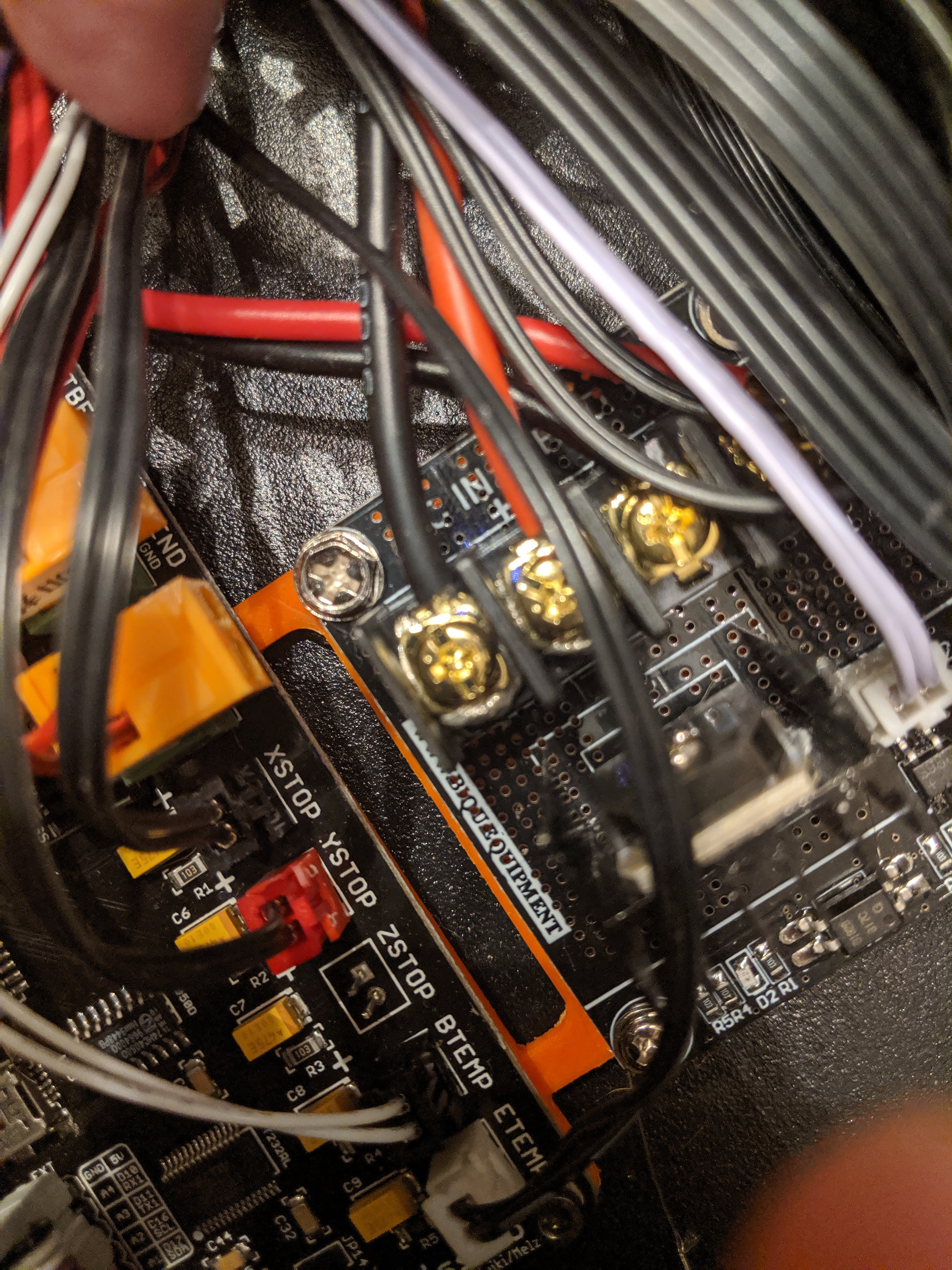
When connecting the BLTouch Z-Stop wire to the connector on the Melzi mainboard you must connect the cable with the orientation shown. If you connect this cable backwards the BLTouch will not function.
Printer Firmware Basics
Like many entry-level printers, the i3 is commercial variant of a RepRap printer design. RepRap printers are 3d printers that have freely available designs and contain a large number of parts which can be 3d printed. 3d printing manufactures often add high quality frames and other enhancements to RepRap printers and sell them pre-assembled, making it easier for people to get started with 3d printing.
The i3 is based on one of the most popular RepRap 3d printer designs, the Prusa i3.
Similar to a computer, a 3d printer has a mainboard and software. The software running on the mainboard is known as firmware and the mainboard can be categorized as a single-board microcontroller. A 3d printer's motors, temperature, and LCD are all controlled by the mainboard and firmware. Because the i3 does not ship with automatic bed leveling it was unnecessary for the manufacture to include bed leveling software in their firmware. If you wired in a bed leveling sensor to a i3 and don't change the firmware then your printer won't know how to use the sensor.
To change out the firmware you first have to know which ones are compatible with your 3d printer. Firmware compatibility is largely determined by the mainboard installed in the printer. Some people will completely change out the mainboard, and therefore the firmware, to add bed leveling support. For our purposes we'll assume you'll want to keep the original mainboard.
The mainboard used in this printer known as a Melzi and is compatible with a Sanguino single-board microcontroller. The Sanguino is basically a slightly more powerful Arduino with more pins and memory. That means you can use normal Arduino software tools, with a Sanguino plugin, to program the Melzi mainboard in the i3 printer.
Adding a BootLoader to the Melzi Mainboard
TIP: Take pictures before disconnecting any cables and also use masking tape tap to label any wires you disconnect from your mainboard. Some wires are not unique in appearance and the masking tape can be written on to identify where the wire should connect to.
Before flashing new firmware to the Melzi mainboard you'll need to upload a bootloader to it. This is the part of the process that requires the Ardunio Uno.
You'll need to download and install the Ardunio IDE. Version 1.8.10 was used when writing this tutorial.
There is already an excellent video for flashing bootloader on the i3 and hardware disassembly. Follow the instruction in that video to wire the Uno to the Melzi and flash the bootloader. You can ignore the part about the Repetier, we'll be using Marlin.
Once the bootloader is flashed you can disconnect the Uno, it won't be used anymore. You will be directly connecting the Melzi to a USB port on your computer.
In order to flash the firmware to the Melzi mainboard you must select the correct COM port in the Arduino IDE. For me the COM port wasn't showing up. The reason was that I had previously only printed using the SD card and by connecting the printer to a dedicated OctoPrint server and the printer was listed as an unknown FT232R usb uart device in the Windows Device Manager. To get the printer to show as a COM port you may have to install the drivers from https://www.ftdichip.com/Drivers/VCP.htm if you have not previously done so.
Marlin Firmware
Download and extract the latest stable release of Marlin which as of this time is 1.1.9.
There are several good videos that introduce you to the Marlin firmware. I'd suggest watching https://www.youtube.com/watch?v=lAKyZd63_ns and https://www.youtube.com/watch?v=U8_ldMckGDE. Watch both videos completely. Of special interest, 6:44 to 7:04 of the second video discusses slimming (disabling features) so that other features like BLTouch support can have room to be enabled in the limited storage space of the ATmega1284.
Configuring the Arduino IDE for the Melzi Mainboard
In the Arduino IDE, open File, select Preferences, in the Additional Boards Manager URLs field add https://raw.githubusercontent.com/Lauszus/Sanguino/master/package_lauszus_sanguino_index.json and press the OK button.
Next open the Tools menu, select Board:, and then select Boards Manager. In the Boards Manager search for Sanguino. Select the latest version (1.0.3 at this time) and press Install. After the install completes you can close the Board Manager. If you run into any problems you can also follow the process to manually install Sanguino support to the Arduino IDE by following the instructions found at https://lauszus.com/Sanguino/.
Next open the Tools menu, select Board:, and then select Sanguino. Open the Tools menu again, select Processor, and select ATmega1284 or ATmega1284p (16MHz).
You also need to install the U8glib library in the Arduino IDE using the library manager. I used version 1.19.1.
i3 Marlin sample configurations
I started with the Marlin default Configuration.h and made i3 specific changes. To figure out what others are changing for their i3 printers I evaluated the following configurations:
- https://reprap.org/forum/read.php?415,809741
- https://www.reddit.com/r/3Dprinting/comments/8o3wg8/installing_marlin_on_maker_select_v2/
- https://gist.github.com/jdembowski/f3d2f9da41519aa73ecc591353e09bd5#file-configuration-h
- https://github.com/swindonmakers/Wanhao-i3-Firmware/blob/master/Marlin/Marlin/Configuration.h
- https://github.com/andyrblank/Marlin-Maker-Select-V2/commit/b02401164dd9a07cf3acdf336aa34a1e5b47c870#diff-8270513bcf2a548cd418cdfe123f27d3
- https://github.com/fdev31/Marlin/commit/c64f5b4ea4ef54fff9599f73dc2c0e75a45aa8ef#diff-8270513bcf2a548cd418cdfe123f27d3
The result of combing through all these configuration files and various testing are the configuration files I've created which can be found at https://github.com/chasetec/Marlin/tree/1.1.x/Marlin/example_configurations/Wanhao. I'm sharing the links to the other configuration files in case one of the differences in them help you with any problems you might have.
For example my LCD was garbled until adjust the ST7920_DELAY values to those found in the chasetec repo. But from what I've seen it looks like different values have worked for others. The 3 sample configurations I'm providing are:
- Duplicator i3 - A Marlin firmware configuration with minimal changes to the Marlin default configuration, only contains changes to make Marlin work on the i3.
- Duplicator i3 leveling assist - Enables additional Marling features including manual bed probing and corner leveling.
- Duplicator i3 bltouch - Configuration changes for an i3 with connected BLTouch probe. Unlike many i3+BLTouch examples, this configuration preserves SD card and LCD support.
Flashing Marlin
Once your printer has a bootloader the process to flash Marlin it simple.
- Download the Configuration.h and Configuration_adv.h files you want to use from https://github.com/chasetec/Marlin/tree/1.1.x/Marlin/example_configurations/Wanhao and save them in the Marlin-1.1.x/Marlin directory you extracted from the Marlin ZIP download. You want to replace the existing copy of those files.
- Double-click on the Marlin.ino file to open Marlin in the Arduino IDE.
- From the tools menu, select the correct board [Sanguino], processor [ATmega1284 or ATmega1284p (16MHz)], and COM port.
- Adjust the
#define X_PROBE_OFFSET_FROM_EXTRUDERand#define Y_PROBE_OFFSET_FROM_EXTRUDERvalues in Configuration.h to match your mount. - Click the Upload button to build and upload the firmware.
If your LCD display is garbled you may need to try different values for the ST7920_DELAY_2 and ST7920_DELAY_3 defines.
If you flash the BLTouch configuration before wiring in your BLTouch you'll hear persistent fast beeping. This is normal since the configuration repurposes the speaker pin for the BLTouch and the firmware is attempting to communicate with the BLTouch and the signals are still going to the speaker.
Additional Post-Install Configuration
After getting the firmware and BLTouch installed there are still a couple step you'll need to perform.
PID Tuning
After installation its recommended that you tune the power setting for the hotend and bed, this is known as PID tuning. You'll have to run a couple GCODE commands, adjust the Configuration.h files and reflash your printer.
X and Y Offsets
I found that the X_PROBE_OFFSET_FROM_EXTRUDER AND Y_PROBE_OFFSET_FROM_EXTRUDER values mentioned in the thingverse pages for BLTouch mounts are not always exact. And you REALLY need the exact values if automatic bed leveling is going to work correctly. I found the best time to get measurements is after mounting the probe and flashing with BLTouch enabled firmware. If you deploy the probe with M280 P0 S10 and lower the Z axis to where it almost touches the bed you can place a sticky note or piece of tape on the bed to mark the position. Write down the current X and Y position. Next, stow the probe with M280 P0 S90 and lower and position the nozzle tip on the spot you marked. Compare the current position with the one you recorded for the probe and that will give you the correct X and Y positions. X to the left of the nozzle is negative and Y to the front of the nozzle is negative.
If you get different values than those in your Configuration.h file you should update the values and re-flash the firmware.
Z Offset
The Z offset is best set through measurement and saving the configuration. I wouldn't bother setting this as a fixed value in the firmware's Configuration.h.
These commands assume that you've got the X and Y offsets set correctly and you have Z_SAFE_HOMING defined (it is in the same configuration file). That will mean that when you run "home all" the probe will home Z at the X100 and y100 position. Calculating the Z offset by measuring the distance to make the nozzle pass the paper test at this exact same position is important. Otherwise you might get an incorrect Z offset if your bed is not level.
You can use the Arduino IDE serial monitor or the OctoPrint interface to run these GCODE commands.
M502; set defaults
M500; save defaults
M851; show existing offset, should be zero
G28; home all
M211 S0; deactivate software endstops
M114; report postion
G1 X100;
G1 Y100;
G1 Z0; go to z 0
G0 Z-0.10; test with paper, repeat with lower values until paper drags
M114; report postion
M851 Z-1.90; set z offset. REPLACE -1.90 with your value
M500; store offset
G28; home with new offset
G29; level bed
M500; store bed leveling
M211 S1; re-enable software endstops
Automatically Running Bed Leveling
You can automatically run the bed leveling every time you print. By adding G29 to the before printing GCODE in your slicer program. Just make sure that any home commands (G28) happen before the G29. If you run G28 after G29 it will turn off bed leveling.
The before printing GCODE I'm running is designed for use in CURA and is based on code found on Reddit.
M140 S{material_bed_temperature_layer_0} ; Set Heat Bed temperature
M190 S{material_bed_temperature_layer_0} ; Wait for Heat Bed temperature
M104 S160; start warming extruder to 160
G28 ; Home all axes
G29 ; Auto bed-level (BL-Touch)
G92 E0 ; Reset Extruder
M104 S{material_print_temperature_layer_0} ; Set Extruder temperature
G1 X1.1 Y20 Z0.3 F5000.0 ; Move to start position
M109 S{material_print_temperature_layer_0} ; Wait for Extruder temperature
G1 X1.1 Y200.0 Z0.3 F1500.0 E15 ; Draw the first line
G1 X1.4 Y200.0 Z0.3 F5000.0 ; Move to side a little
G1 X1.4 Y20 Z0.3 F1500.0 E30 ; Draw the second line
G92 E0 ; Reset Extruder
G1 F{speed_travel}
G1 Z2.0 F3000 ; Move Z Axis up little to prevent scratching of Heat Bed